Too busy to read the manual? This quick guide to automotive oscilloscopes helps you track down faults in electronic fuel injection systems.
With fuel injectors costing £25 to £100 each, and throttle body injectors around £150, swapping parts is an expensive way to diagnose injection faults. A tool that can detect faulty injectors will soon pay for itself.
Scan tools are only as smart as the engine’s electronic control unit (ECU), which often confuses injector faults with sensor faults. Multimeters are cheap, but too slow to see injectors opening and closing. An oscilloscope is far more versatile: it displays the changing voltage on the switched side of a fuel injector and, with a current clamp, can even show the current through the injector coil. You can also use it on all the other electrical components in the vehicle.
Vital Statistics
Here are some of the specifications that matter when choosing an automotive oscilloscope:
- Vertical resolution. How many voltage levels the scope can display. Eight bits (or 256 levels) are enough to give a rough guide. For better accuracy, choose ten bits (over 1,000 levels) or twelve (over 4,000 levels).
- Sample rate. How fast the scope can measure voltage. Choose at least one million samples (1 megasample) per second (or 1 MS/s) to catch the fastest-moving waveforms.
- Buffer size. How many samples the scope can store. A buffer size of 1,000 (1 k) samples is inadequate at high sampling speeds. Aim for 32,000 (32 k) or more.
Saturated-Drive Injection
In saturated-drive injection, the ECU applies the full battery voltage to the injector, which has either a high internal resistance or an external resistor. The total resistance of the injector plus any resistor is around 10 to 16 ohms. This is the most common system in production engines.
Our first measurement will be the voltage waveform of a single injector. Automotive scopes have a menu of options for the most common measurements, like “injector voltage”, “injector current” and “crankshaft sensor”. Select the “multi-point injector (voltage)” menu option.
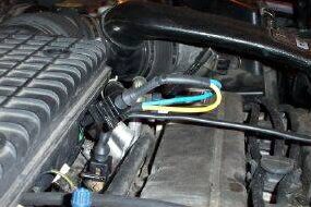
Breakout lead attached to injector |
Choose Your Weapon
First, you need to choose a probe. Often, this is as easy as picking one that fits the component. Sometimes you need to be more careful; otherwise you could see no signal or even damage your scope. Check your scope’s manual or on-line help for advice.
If your injectors have standard connectors, you can use a breakout lead to pick up the injector voltage without having to strip or pierce any wires. Otherwise you can use a back-probing kit, which is a pair sharp pair of pins that you push into the back of the connector, or you can use insulation-piercing probes.
Don’t Blow a Fuse
Always connect the scope’s ground (black) wire to the vehicle’s earth, never to the injector. You can then safely probe with the signal (red) wire until you find the right terminal on the injector.
On the Grid

Start the engine and a voltage waveform will appear on your scope. The column of numbers on the left under the letter V is the voltage scale ― it shows the voltage on the switched side of the injector. The bottom of the scale represents minus 10 volts, with 90 volts at the top. The row of numbers running from 3 to 6 along the bottom is the time scale, where the numbers represent thousandths of a second (milliseconds or ms) from the trigger point. The software has automatically set the trigger for us.
Thin Blue Line
The waveform itself is the blue line. The switched side of the injector starts on the left at about 15 volts (battery voltage). A short time after the intake valve opens, the ECU switches the injector to earth for about 2 ms. The ECU varies this time depending on the engine conditions ” keeping it short while idling, and increasing it when cold-starting or accelerating. Then the ECU breaks the injector circuit and the energy in the injector coil returns down the wire as a voltage spike. In our waveform, the spike has a flat top at 60 volts, showing that the ECU’s protection circuit has limited it to prevent damage. The spike then drops smoothly to a steady 15 volts.
Spotting Faults
- If the ECU can’t pull the injector coil down to within half a volt of earth (use the scope’s vertical zoom to see this), it has a faulty driver.
- If the spike is missing or too small, the injector coil is faulty.
- If the spike is too high, the ECU protection circuit has failed.
- The ECU adjusts the pulse width to control the engine power. You can easily test this by watching the injector pulse widen as you blip the throttle or increase the idle speed.
Current Affairs
The voltage waveform can show basic faults in the injector coil and the ECU, but it can’t find a stuck injector. A few vehicles have injector-position sensors, but generally you can check by measuring the injector current. If you have an automotive PC oscilloscope, just select the “injector (current)” option from the menu and follow the instructions. The two-pin breakout lead is handy here, as you can clamp the current probe on it without disturbing the vehicle’s wiring.
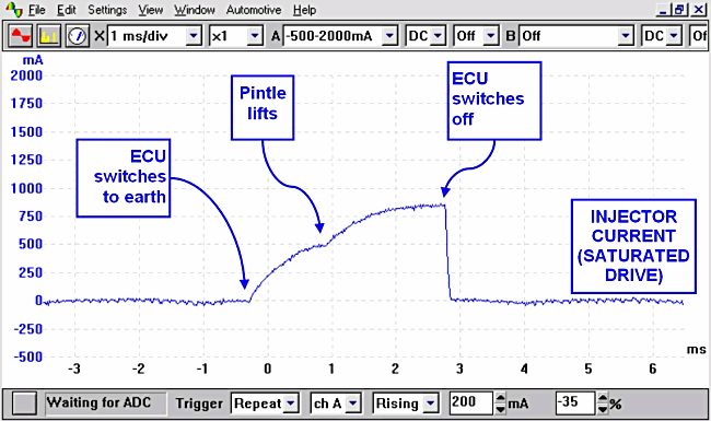
The current waveform has a vertical scale of thousandths of an amp (milliamps or mA), and the same time scale as the voltage waveform. At time zero, the ECU switches the injector on. The current rises smoothly to about 850 milliamps, until the ECU switches the injector off.
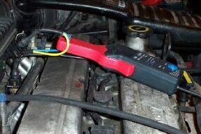
Current clamp attached to breakout lead |
More Faults
- Notice the small dip in current at 1 ms ― this is when the injector opens. Only the current waveform shows you this. If there is no dip, the injector is stuck.
- If the dip is later on one injector than on the others, that injector is slow, causing the cylinder to run lean.
- If the current pulse is rectangular instead of curved, the injector is shorted.
- No current means the injector coil is probably open-circuit.
其它案例和文章 >
|